Generator Principle
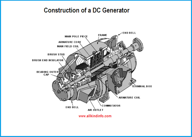
An electrical generator is a machine which converts mechanical energy or power into electrical energy (or Power). The energy conversion is based on the principle of production of dynamically induced e.m.f.
Whenever a conductor cuts magnetic flux,dynamically induced e.m.f. is produced in it according to Faraday's Laws of Electromagnetic induction. This emf causes a current to flow if the conductor circuit is closed. So there are two basic parts of an electrical generator are
1: a magnetic field 2 : a conductor or conductors which can so move as to cut the flux.
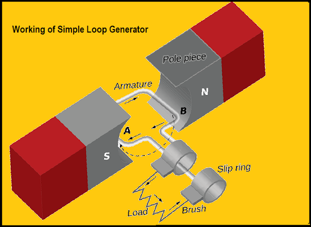
Construction of simple loop generator.
A single turn rectangular copper coil ABCD rotating about its own axis in a magnetic field provided by either permanent magnet or electromagnets. The both ends of the coil is fastened to two slip-rings a and b which are insulated from each other and from the main shaft.
Two collecting bushes of carbon or copper press against the slip-rings. Their function is to receive the current induced from the coil and to pass on it to external load resistance R. The rotating coil can be called "armature" 'and the magnets are as "field magnets".
Working of simple loop generator
Imagine the coil is to be revolving in clock-wise direction.As the coil assumes successive position in the field, the flux connected with the charge. Hence the emf is produced in it which proportional to the rate of change of flux linkage. When the plane of the coil is at the right angles to lines of flux i.e when it is in position,l,then flux connected with the coil is maximum but rate of charge of flux linkage is down. It is due to in position , the coil side AB and CD do not cut the flux, rather they slide along them.(they move in parallel).
Hence there is no emf produced in the coil. If we consider no emf in the coil at the starting position, the angle of rotation will be calculated from the position. As the coil continues revolving more , the rate of change in the flux linkage increases till the position 3 is reached where angle is 90 degrees. Here the coil plane is horizontal and parallel to the lines of flux. As seen the flux linked with the coil is minimum but rate of change of flux linkage is high. Hence, the maximum emf is induced in the coil when in this position.Next quarter from 90 to 180 degrees the flux linked gradually increases but rate of change of flux decreases. From 180 to 360 degrees revolution the variation in the magnitude of emf are similar to those in the first half revolution.For making the flow of current unidirectional in the external circuit i, the slip rings are replaced by split-rings.The split rings are conducting cylinder typed material which is used to cut two segments insulated from each other by a thin sheet of mica or other insulated material.


Post a Comment