March 2016

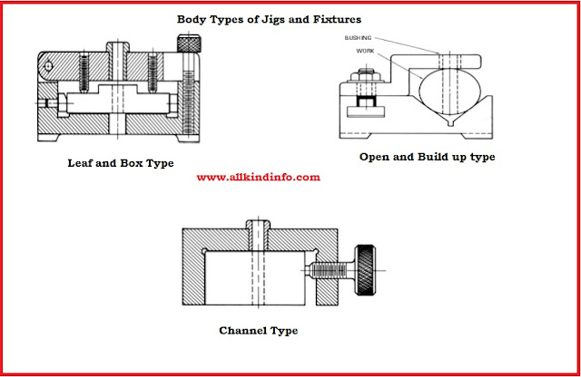
body types of jig and fixtures

Different elements of jigs and fixture are commonly used in the workshop and their uses and functions are as follows.

1 : Body

Material of jig body is made from cast iron manufactured through casting or fabrication operations. Body slabs and bars are fabricated by welding and then heat treated to decrease the stresses. Its main function is to support the work piece and hold the job.Different body types of jigs and fixtures are as follows.

(i) Plane Type Body

The most simplest form of body is called plane type body. When holes to be drilled in a simple way this type of body could be used. Drilling operation can be performed without or with the guide bushes.

(ii) Channel Type Body

This type of body contains a channel or more than two channels. Channel are made from steel and Cast Iron materials. 

(iii) Box Type Body

When many holes are required from different sides. Template plates can be used to drill from any plane.One side of the box is mounted with a lid, which is helpful for loading and unloading the job.

(iv) Built Up Type Body

Dowels, screws and locating pins are used in this type of body. Material of this body is a standard steel. Blocks are used to locate and position the job.

(v) Leaf Type Body

This is the most advanced and modified type of body. A fulcrum type lid is adjusted on the top of the body.It is used in case of measured large work pieces where it may necessary to hold the whole component in the jig. 

2: Locating Devices.

Different types of pins are used to locate the component in the jigs and fixtures body.  These pins are made from hardened steel. Shank or neck of the pin is press fitted into the jigs and fixtures body.Various types of locating pins are.

(i) Support Locating Pins

These are also called rest pins, which are used to adjust the work piece. Support locating pins have two kinds. First type is called fixed type, which are used to locate the face either round, curved or flat. Spherical or round head insure stable locating.Second type of pins are adjustable type, which are used where dimension of work piece can vary. These are mostly used in forging,sand casting.
support locating pins adjustable and fixed type

(ii) Locating Pins

When Finished holes or reaming is required then these pin are used. These pin are also used to locate the work piece as well. Conical and cylindrical types of locating pins are used in the work shop.
locating pins types
jigs locating pins

(iii) Jack Pins

These pins are also called spring pins. Purpose of these pins are to locate the job whose length is subject to variation. Spring allows the compression and locate the work piece easily. Locking screw type of jack pin is more secure when job is adjusted and then pin can lock whole face of the work piece.
jack pins

basic drawing elements

Drawing is the language of the engineer and lines are the alphabets of the language. Every line describes it self its function. In auto cad lines are used to draw the object outline and other functional lines. For Detail of lines, their types and their function to read click here.
To Set the different kinds of lines in autocad follow the instruction as below.
Step 1: 
Click on the by layer tab, drop down list will be appear. Here you will see that only two to four lines already exists. For load more lines click on the other
.
Step 2 :
 Another menu will be appear, here click on the load button and select any line you want.


Step 3:

These selected line will be appear in the by layer tabs. Now pick the lines which you want to apply in the drawing. 
Step 4: 
Then chose from by layer menu line type and click it to apply. Chose any color from the color menu and apply your drawing and your drawing will be completed.

Drilling jigs and fixtures

Drilling Jigs are utilized to machine holes in mechanical items to get positional exactness of the gaps solidify drills bushes or jig bushes used to locate or guide the reamer or the drill tool.  In connection to the work piece these these guide bushes are not necessary but these prove to be economical and technical. The position of the jig into which the solidify/hardened bushes are mounted is called bush plate. Drilling jigs are either clipped to the work piece in which holes are to be bored or the work piece is housed and clamped in the jig or fixture body. If many holes  to be drilled , the drill jig is made to slide on the table to drilling machine. Such a drill jig is moved by hand into position under the drill so that the drill radially enters the bush.During this operation the jig is held by hand. If the  drill size is sufficiently larger to create a high torque , either stops ought to be given or the drill jig is clipped to the table of the drilling machine. A drill jig  is given feet which lay or slide on the table of drilling machine. These feet ought to be outside of the cutting powers, in this way giving strong backing.Drilling jigs make practically the drilling of holes at higher velocity with more noteworthy precision and with less talented laborer. At that point is conceivable when the holes are laid out and drilled by hand.Then is possible when the holes are laid out and drill by hand. Also they produce inter changeable parts because each part drilled in a drilling jig should have the same hole pattern as every other parts.It is clear that during drilling operations chips or burs  will be created. The chip or bur created at the short of the hole is smaller than the created at the end of the hole.The first type is called minor burs and second type is called major burr. (when the drill makes through the material).At the point when planning a drill jig these two sorts of burr ought to be thought about since they might bring about trouble in emptying the work piece from the jig or fixture after a hole has been bored.
drilling jig


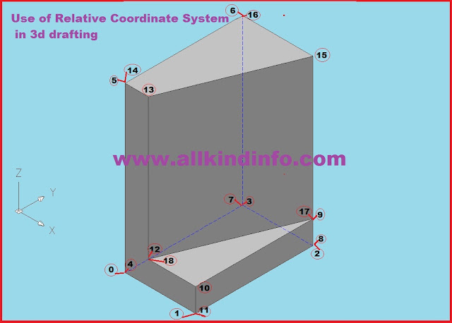
3d autocad drawing
Before you draw a 3d drawing ucs (user coordinate system icon) will be at this position(just in x and y coordinates)
3d drafting techniques
Then Click on the SE (South East) Icon placed on the view tool bar. After clicking the SE tab your UCS will show 3 Coordinates (X,Y and Z) shown in blew figure.
3d drawing in autocad

Now follow the below mentioned instructions and draw a 3d drawing in autocad.
Step by Step instructions.
L enter and click on any point at the drawing area.

  1. @ 150 , 0 , 0 
  2. @ 0 , 250 , 0
  3. @ -150 , 0 , 0
  4. @ 0, -250, 0
  5. @ 0 , 0, 350 
  6. @ 0 , 250 , 0
  7. @ 0 , 0 , -350
  8. @ 150 , 0 , 0
  9. @ 0 , 0 , 50
  10. @ 0 , -250 , 0
  11. @ 0 , 0 , -50       Return back by writing   @ 0 , 0 , 50
  12. @ -100 , 0 , 0
  13. @ 0 , 0 , 300
  14.  @ -50 , 0 , 0       Return back    @ 50 , 0 , 0
  15. @ 100 , 250 , 0
  16. @ -150 , 0 , 0      Return back    @ 150 , 0 , 0
  17. @ 0 , 0 , -300
  18.  @ -100 , -250 ,  0

broaches

Broach
A broach is a multi point cutting device having a progression of cutting teeth or edges which bit by bit increment in size from the beginning or entering end to the backside. These surfaces are utilized for machining either outer or inward surfaces. These surfaces might be created level or roundabout. In proposing, the suggest is pushed or pulled over or through a surface of work piece, Each tooth of the apparatus. A slight cut from surface proposing of inside surface is called inner or gap suggesting and outside surfaces is called surface broaching.

Material of Broach
As being among the cutting tools, broach are also made from high speed  steel(HSS),which are having the usual cutting tool properties like strength,hardness,toughness and heat resistance.Now a days for better quality and  enhance cutting speed cemented carbide tip or segments are widely used in the workshops.

It is utilized to machine an inside hole. The broach is held by puller at the shank end. The front rake angle alludes a rake edge of a solitary point decreasing of the edge (relief angle) is given to anticipate rubbing of the device with the work piece. 

High speed steel (Hss) material is generally used to make the propose. It is additionally raised carbide of expendable supplements or at some point utilized for front lines then machining cost iron parts, which requires close resilience. Carbide apparatuses are additionally used to preference on steel cutting. A suggest might be either gathered or developed structure shells.
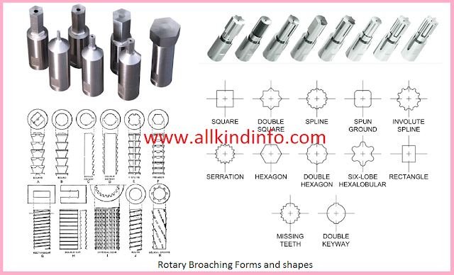
Form/shapes of Broaches
According to work and cutting speed there are many types of broaches forms such as in hexagon,round,rectangular,star,octagon etc. Different forms of broaches are shown in figure.
forms of rotary broaches

twisted drill parts

The Drilling tools are called drills which are used to make round holes in the work piece. There are three  most commonly used drills as follows.

Flat Drill

Simple in shape and has two cutting edges at the angle of 60 degree.

Straight Fluted Drill

This drill is used to make holes in brass,copper and other soft metals. This drill has zero rake.
various types of drills

Twist Drill

It is an end cutting tool with two or three cutting lips. Cylindrical shaped body consists of grooves with cutting edges. The grooves are called flutes. Other parts of twisted drill are

1: Point

Cone shaped and provide cutting to the metal.It has three major parts

(i) Heel

Cutting edge back point of the back portion of the point is a heel of drill.

(ii) Lips

Cutting edges of the drill bits are called lips.

(iii) Dead center

Extreme tip of the twist drill bit is called dead center.This should be placed exact center of the center punch mark.

2: Body

Area between the point and the shank is the body of the drill.It consists of three major parts.
[ads-post]

(i)Flutes

Two or more groove with spiral shape that run the body of the drill is called flutes. Function of the flutes are to provide lubricants/coolant  flow to the end point, cut the chip easily and help from the cutting edge to the drill point.

(ii) Margin

Narrow strip back from the flutes.It is the diameter of the whole drill bit.

(iii) Body Clearance.

Part of the body which reduces friction between the wall of the hole and the drill.

3: Shank

The portion of clamping the drill in the spindle is called shank.It may be straight or tapered angle.

Angles of Twist drill

Point angle

Angle included between the two lips projected upon a plane parallel to the drill axis and parallel to the cutting lips.Its usual value is 118 degree but it can varies from metal to metal.

Lip Relief angle.

Angle created by flank and a plane at right angles to the drill axis. It value is 12 to 15 degree.

Chisel edge angle.

It is the obtuse angle included between the chisel edge and the lip as viewed from the end of the drill. The value of this angle varies 120 to 135 degree.
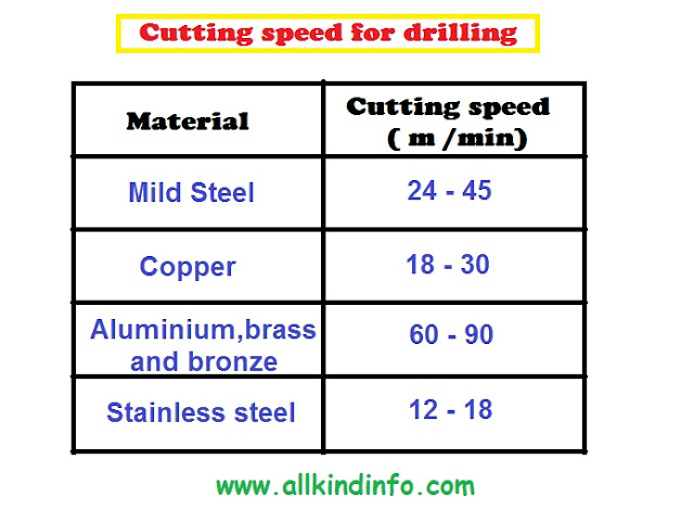
cutting speed of drilling

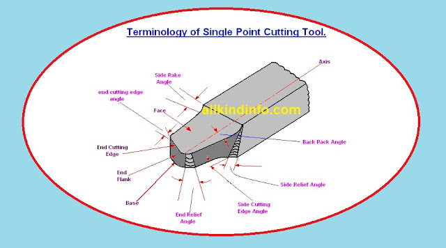
Single point cutting tool terminology


1: Side Cutting Edge Angle: 


The point between side cutting edge and the side of the tool shank is called side cutting edge angle. It is frequently alluded to as the lead point. 

2: End Cutting Edge Angle: 


The angle between the end turning edge and a line opposite to the shank of the tool shank is called end cutting edge angle. 

3: Side Relief Angle: 


The angle between the segment of the side flank instantly underneath the side front line and a line opposite to the base of the tool. 

4: End Relief Angle: 


The angle between the end flank and the line opposite to the base of the tool is called end relief angle. 

5: Back Rake Angle: 


The angle between the substance of the face of tool  and line opposite to the base of the apparatus measures on opposite plane through the side front line. It is the edge which measures the incline of the of the face of the tool from the nose, towards the rack. If the slope is downward the nose it is negative.

6: Side Rake Angle: 


The point between the face of the tool and a line parallel to the base of the tool measured on plane and to side edge. opposite to the base and the side edge. It is the angle that measure the slope of the tool face from the cutting edge, if the slope is towards the cutting edge it is negative side rake angle and if the slope is away from the cutting edge, it is positive side rake angle. If there is no slope the side rake angle is zero.


electric field image of attraction and repulsion


Electric Field

There is a charge of force around the medium, acts on a negative or positive charge when placed in the medium. If the charge is a huge , then it may create such a large stresses and causes the electrical damage to the medium, followed by the passage of an arc discharge.
The place in which the stresses leaves or in which the forces act, is called an electric field or electrostatic field.
These stresses are represented by imaginary lines of forces. The direction of the lines of forces at any points is the direction along with a unit positive charge placed at that point would move if free to do so. According to Faraday the electric field should be imagined to be divided into tubes of force consisting of fixed number of lines of force.
He considered these tubes having elasticity and the property of contracting longitudinally the repelling laterally. Fundamentals of this theory it becomes easy to explain 
(i) Why unlike charges attract each other and try to come nearer to each other.
(ii) Why same charges repel each other and try to go from each other.
However, it is more common to use the term lines of force. These lines are supposed to emanate from a positive charge and end on a negative charge. These lines always enter or leave a conducting surface normally.

Electrostatic induction.

It is a common practice when a charge body comes near uncharged body, it acquires some charge. This phenomenon of an uncharged body getting charge merely by the nearness of a charge body is called as induction. When a positively charged body A is placed close to the perfectly insulated uncharged body B, It is found that the end of B nearer to A gets negatively charged whereas further end becomes positively charged.
The positive and negative charge of B are known as induced charges. However the positive charge on the further end of B is called fee charge. In other figure when body B is earthed by a wire, the positive charge flows to earth leaving negative charge behind. If next A is removed, then this negative charge will also go to earth, leaving B uncharged. So the results are
(a) A positive charge induces a negative charge and vice-versa.
(b) Each of the induced charges is equal to the inducing charge.
electric induction image


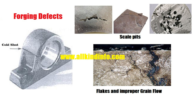
Forging defects, flakes cold shut

Despite the fact that forging process give by a large superior quality item thought compared other manufacturing processes. There are a few absconds that are gently to come a legitimate consideration is not taken in forging  process plan.

A brief depiction of such abandons and their remedial method  is given underneath.

1 : Unfilled Sections

Most of the cases in die cavity the flowing metal does not fill the whole component and causes the unfilled sections. Reason of this defect is lack of in proper forging skills and design combination of forging die.

2: Flakes

These are fundamentally inner cracks brought on by the improper cooling of the huge forging. Fast cooling causes the outside to cool rapidly bringing on inward cracks. This can be cured by taking after legitimate cooling techniques.

3: Cold Shut

When small appears at the corners of the forging, is termed as cold shut. It is also becomes due to the design error of the forging die.

4: Scale Pits

This is seen as irregular ruptures on the surface of the forging. This is primarily caused because of improper cleaning of the stock used for forging. The oxide and scale gets embedded into the finish forging surface. 

5: Die shift

This defect of forging appears when die halve is misaligned, creating the improper shape of the forging component.

6 : Improper Grain Flow

This is also error design in the die, which casuses the flow of metal improper grain stucture of the forging. 

electrostatics


Static Electricity 

Static electricity or electrostatics is the branch of science which deals with the phenomena related with electricity at rest.Generally an atom is electrically neutral i.e. in a normal atom the aggregate of positive charge of protons is equal to the aggregate of negitive charge of the electrons.
Some electrons are removed from the atoms of a body, then it is left with a preponderance of positive charge.It is said to be positively-charged.In other side , some electrons are added to it, negitive charge out-balances the positive charge and the body is said to be negitively charged.So in conclusion we can say that positive electrification of a body results from a deficiency of the electrons whereas negative electrification results from an excess of electrons.

Permittivity of a medium

A certain property of the medium called is permittivity, which acts key role. Every medium is supposed to possess through two permittivities, which are as follow.
1:Absolute permittivity
2: Relative permittivity
For measuring relative permittivity,vacuum or free space is chosen as the reference medium. It has an absolute permittivity of 8.854 x 10⁻¹² F/m

absolute permittivity     ε̻  =  8.854 x 10⁻¹² F/m
relative permittivity      εr  = 1
being a ratio of two similar quantities  εr  has no units.

Now take any other medium,  If the relative permittivity , as compared to vacuum is ε
Then its absolute permittivity is  
                                                           
                                                       ε = ε̻ εr  F/m
 For example relative permittivity of Mica is 5 , then the absolute permittivity is
                        
                                                  ε = ε̻ εr  F/m  = 8.854 x 10–12  x 5
                                                                         = 44..27 10–12 F/m

capacitor figure

Capacitor

Capacitor can be defined as the device which is used to store electrical energy by electrostatic stress in the dielectric. It consists of two conducting surfaces separated from a layer of an insulating medium called dielectric. The conducting surfaces either be round or in rectangular plates or spherical or cylindrical shapes.
A parallel-plate capacitor is shown figure. One plate is fastened to the positive end of the supply and other is joined to the negative end or is earthed. Experimental results indicates that plate B which is earthed , plate A is capable of withholding more charge more than When B is not there. There is momentary flow of electrons from A to B, when a capacitor is put across a battery. 
As negatively charged electrons are withdrawn from A, it acts as a positive and these electrons reaches at B, it behaves as negative. The transient flow of electrons provides rise to the charging current. The strength of charging current is maximum when the two plates are uncharged but it then decreases and finally ceases when p.d.(potential difference) across the plates becomes slowly equal and opposite to the battery e.m.f.(electro magnetic flux)
Capacitor and capacitance

 capacitance

The property of a capacitor to store electricity may be called its capacitance. The capacitance of capacitor may also defined as " the amount of charge required to create p.d. between its plates. 
If we provide Q coulomb of charge to one of the two plate of capacitor and a potential difference of volt V is established the two, then its capacitance is 
                                             
                                                     C = Q/V = charge/p.d. 
so we can say capacitance is the charge required per unit potential difference. Its unit is farad which is equal to coulomb/volt. So 1 Farad = 1 coulomb/volt

Definition of Farad.

Farad is named in the honor of Michael Faraday. Which is defined as the capacitance of a capacitor which needs a charge of one coulomb to establish a p.d. of one volt between its plates.

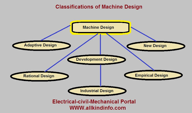
classifications of machine design


Introduction of Machine design

Branch of mechanical engineering/technology which deals with the creation of new and modified(better) machines and improving the existing ones. New and better machine is possible when its overall cost of production and operation is much economical. In machine design it is essential to have the knowledge of strength of material,theroy of machines and workshop technology.

Classifications of machine design.

Machine design can be classified into following types.

1: Adaptive design

In many cases, the designer's work is connected with adaptation of existing design. It is fundamental and basic designing procedure which is required no extra knowledge or skills. In this type of design, designer makes small modification in the existing machine or product.

2: Development design

This type of design requires much more design skills and scientific training to produce a new and modified machine. In this case, designer starts from the the existing designs but finished product can be different from the original one.

3: New design

This is unique kind of designing which requires much more technical ability, creative mind and lots of research. This type of design can only those handle which have these personal qualities.

4: Rational design

This class of design requires the ability of principles of mechanics and mathematical expertise.

5: Empirical design

This type of machine designing procedure requires empirical formulas and past practice of machinery development.

6: Industrial design

This kind of design depends on the production aspects to produce any machine parts used in the industries.

autocad 3d tool bars

To start Auto cad 3d drafting we have to know the basic tool bars of the auto cad 3d.
In this tutorial we discuss the basic tools bars and there introduction and how to set them in the graphical window.

View Tool Bar.

It is the most important tool bar related to 3d drawing. This tool bar helps to convert 2d drawing into 3d drawing. It has 6 tabs used in 2d drawing selection and 4 tabs used for 3d drawing selection. 

UCS II

This tool bar is used to draw the drawing from the perspective. View Selection in the 3d plays key role to build a smooth drawing. View selection of the drawing can be described into 6 perspectives.
1: Top  2: Bottom 
3: Front 4: Back
5: Left   6: Right
6 view 3d drawing


Modeling 

This tool bar is essential to draw the common figures such as cone,cylinder,wedge,torus,box etc. This tool bar consists of two properties. First property of tool bar is to draw and second property of the tool bar is to modify the drawing. Modification features are like extrude faces,loft and sweep etc.

Visual Styles.

This tool bar is related to the object property by means of visual styles. You can select any method to replace your drawing style like in wire frame or in solid shaped. 

Orbit

This tool bar is extra tool bar to view the drawing from its 6 perspectives as we mentioned in the above view tool bar. You can check your drawing side by rotating with the help of this orbit tool bar.

punching,lancing,blanking etc sheet cutting operations


1: Blanking: 


Blanking is the operation of cutting a flat shape from sheet metal. The item punched out is known as the "blank" and the required result of the operation the gap and the metal abandoned is disposed of as waste. 

2: Punching or Piercing: 


It is a cutting operation by which different holes openings are made in sheet metal. Punching is like blanking aside from that in punching, the gap is the fancied item. The material punched out from the opening being waste. 

3: Notching: 


This is cutting operation by which metal pieces are cut from the edge of the sheet , strip or blank. 

4: Perforating: 


This is a procedure by which numerous gaps are little and near one another are cut in a level sheet metal. 

5: Trimming: 


This operation contains of cutting undesirable excess of material from the outskirts of a formerly framed segment. 

6: Shaving: 

The edge of a blanked part are generally rough, uneven and non square.
Precise measurements of the part are acquired by removing a thin segment of metal along the edges. 

7: Slitting: 


It alludes to the operation of making incomplete gaps in a work piece. 

8: Lancing: 


This is a cutting operation in which a gap is mostly cut and afterward one side is twisted down to frame a kind of tab. Since no metal is really evacuated and there will be no scrap. 

9: Nibbling: 


The operation , which is utilized for just little amounts of segments, is intended for removing level parts from sheet metal. The level parts from easy to complex shapes. This operation is by and large substituted for blanking. The part is typically moved and guided by hand as the constantly working punch removing at the edge of the desired shape.

Forming Operation

1: Bending:

In this operation; the material in the form of flat sheet or strip is uniformly strained from a linear axis which lies in the neutral plane and perpendicular to the length wise direction of the sheet or metal.

2: Drawing:

This is a process of forming a flat work piece into a hollow shape by means of a punch which cause the blank into a die cavity.

3: Squeezing:

Under the operation, the metal is caused to flow to all portions of a die cavity under the action of comprehensive forces.

law of resistance


Resistance.

The property of a substance by which it restricts the flow of electricity (electrons) through it. Metals,acids and salts solutions are good conductors. Among metals, silver, copper and aluminium are very good conductors of electricity.When electrons flow through the molecules or the atoms of the conductor, collide to the other atoms and electrons and generate heat. Those elements which offer relatively greater difficulty  to the passage  of these flowing electrons are said to be poor conductors of electricity.
Dry wood, rubber,PVC (polyvinyl chloride) and glass are poor conductors examples. Good insulators are fibrous substances like paper and dry cotton, mineral oil free from acid and water.

Unit of Resistance.

Unit of resistance is ohm, it can be defined as " a conductor having a resistance of one ohm when it permits one ampere current to flow through it when one volt is impressed across its terminals. For high resistance insulators bigger units  are used. Its symbol is (omega) Ω.

Laws of resistance.

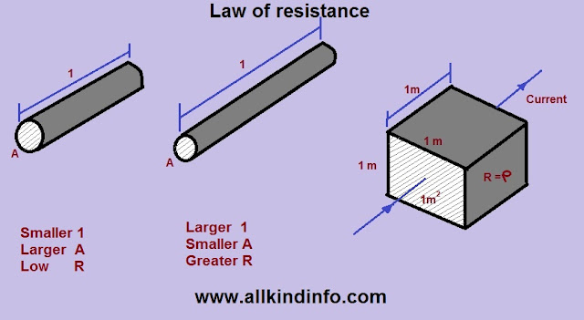
The resistance R offered by a conductor depends upon the following factors which are known as laws of resistance, which are 
1: It change direction as its length l.
2: It varies inversely as the cross-section A of the conductor.
3: It depends on the nature of the material.
4: It depends on the temperature of the conductor.
So we can say 
                             R = ρ . l/A
where ρ is a constant depending on the nature of the material of the conductor and is known as specific resistance or resistivity.

Resistivity

Specific resistance or resistivity of a material may be defined as the resistance between the opposite forces of a meter cube of that material.
S.I unit of resistivity is ohm-meter.(Ω.-m)
 Mathematically
                           ρ = A (meter²) x R (ohm)/ l (meter)
                      = AR/l 


The idea of Electric potential

A simple voltaic cell shown in figure, It contains of copper plate (Anode) and a zinc plate (Cathode) placed in a dilute sulfuric acid stored in suitable vessel. The chemical action taken placed  within the cell causes the electrons to be removed from the copper plate and to be deposited on the zinc plate at the same time.
Transfer of these electrons is completed with the help of dilute sulfuric acid, which is named as electrolyte. Zinc side becomes negative side due to deposit of electrons and copper side act as a positive side due to removal of electrons. The maximum amount of electrons on the zinc side is being attracted by anode but is prevented from returning to it by the force set up by the chemical action within the cell.
When two electrodes are connected by a wire externally, then the electrons rush to the anode thereby equalizing the charge of the two electrodes,but due to the chemical reaction a continuous difference in the numbers of electrons on the two electrodes is maintained which keep up a continuous flow of current through the external circuit.The action of the cell is same as water pump working.
When zinc is charged negatively , it is said to be at negative potential with respect to electrolyte, whereas anode is to be said the positive with respect to electrolyte. So in conclusion the copper plate is to be at higher potential than zinc plate. The difference in potential is continuously managed through the chemical action going in the cell which supplies energy to maintain the potential difference.

Common forging operation are follows.

1: Drawing.

This is the operation in which metal gets stretched with a reduction  in the cross sedation zone. For this, a power is to be connected in a course perpendicular to the length axis.

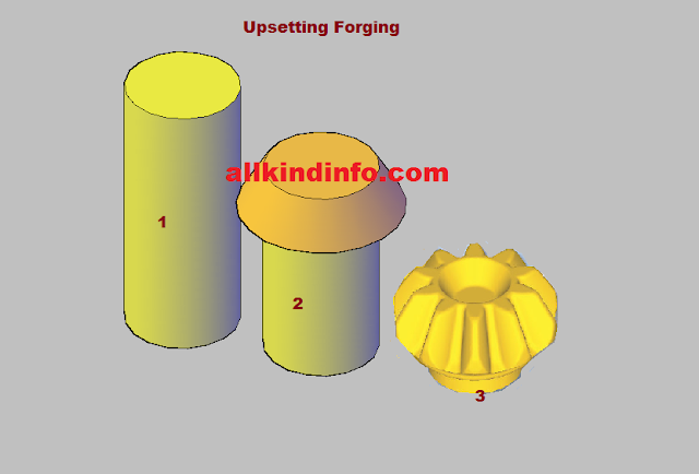
2 : Up setting

upsetting

upsetting methods
upsetting of crankshaft


This is connected to build the cross sectional area of the stock at the expanse of the length. To accomplish the length of annoying power is connected in a course parallel to the length axis, For example shaping of a bolt head.

3: Fullering

It a like to  material cross-area is minimized and length expanded. To do this; the base fuller is kept in point gap with the warmed stock over the fuller ,the top  fuller is then kept over the stock and afterward with the sledge hammer, and the power is connected on the top fuller.

4: Bending

Bending  is exceptionally regular producing operation. It is an operation to give a swing to metal bar or plate. This is required for those which have bends shapes.

5: Edging

It is a procedure in which the metal piece is dislodged to the desired shape by striking between two passes on edging is as often as possible as essential drop forging operation.

6: Forged welding

It is a procedure of joining two metal pieces to expand the length. By the squeezing or hammering  then when they are at forging temperature.It is performed in blacksmith shop and consequently is called forged welding.

7: Cutting 

When two pieces of metal rods or plates splits, the process is called cutting.It is done when the material is red hot and it is done by the help of chisel and hammer.

8: Punching

It is a procedure of creating gaps in motel plate is set over the empty round and hollow pass on. By squeezing the punch over the plate the opening is made.

9: Swagging

is done to diminish and complete work for craving size and shape, typically either round or hexagonal. For little jobs top and base swag pair is utilized, where with respect to vast work swag piece can be utilized.

10: flating and setting down

Fullering leaves a ridged surface at work. Indeed, even after a job is forged into shape with a hammer, the signs of the sledge stays on the upper surface of the work piece. To remove hammer imprints and layering and keeping in mind the end goal to get a smooth surface at work, a compliment or set hammer is utilized.

forging


Introduction

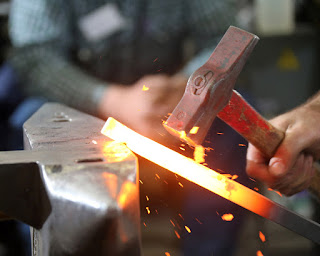
Forging is the operation where the metal is warmed and after that a power is connected to controls the metals in a manner that the required last shape is gotten. Producing is for the most part a hot working procedure through icy manufacturing is utilized now and then.Following are the types of forging.

  • Smith forging
  • Drop forging
  • Press forging
  • Machine forging          
smith forging

Smith Forging

This is the conventional forging operation done transparently or in-straightforwardly bites the dust by the town smithy or present day shop floor by manual pounding or by the force hammer. The procedure includes warming the stock operating at a profit smith hearth and afterward thumping it over the blacksmith's iron. To get the yearning shape the administrator needs to control the segment in the middle of the blows. 
The sorts of operation accessible are fullering,flattering,bending,upsetting and swaging   

Drop forging

drop forging

 This is the operation done in shut impression passes on by means drop hammer here the power for molding the segment is connected in a progression of blows. Drop forging uses a shut impression bite the dust to acquire the longing state of the segment , the forming is finished by the rehashed pounding given to the material in the die cavity. The equipment use for conveying for blows are called drop hammers. The drop forging die consists of two halves. The lower halve of the die is fixed to the anvil of the machine , while the upper halve is fixed to ram. The heated stock is kept in the lower die, while the ram delivers 4-5 blows on the metal spreads and completely fills in the die cavity. When the two die of halves closed the complete is formed. The common items got in drop forging are wrenches, crank shaft, crane hooks etc.
                                                 

Press forging


 Similar to the drop forging , the press forging is likewise done in shut impression dies with the desire that the power is ceaseless crushing sort connected by the hydraulic press.   Press forging dies are similar to drop forging dies as also the process in press forging, the metal is shaped not by means of  a series of blows as in drop forging , but by means of a single continuous squeezing action. This squeezing is obtained by means of hydraulic presses.  Due to the consistent activity of by hydraulic powered presses, the material gets consistently disfigure through out its whole profundity ,the press forging dies with the various impression , such as fuller, bender and finisher impression properly arranged       

Machine forging

Not at all like the press or drop forging where the material is drawn out , machine forging the material is just disturbed to get the craving shape. As it includes the irritating operation some time it is basically called as upset forging. Initially this was produce for making bolts head in a nonstop manner. It is used for making gears, blanks, shafts, excels, and similar parts. Upsetting machine called up setter are generally horizontal acting.                                             

cruicible process method of steel manufacturing


1: Cementation process.

The steel process is called because ferrite in the wrought iron is converted into cementite (Iron carbide).Carbon combines with wrought iron and has its surface covered with blisters.So that this steel is known as blister steel.

2: Crucible process.

This method is homogeneous,free from slag ,dirt and much superior to cement steel.It is also known as crucible steel.

3: Bessemer process.

bessemer process of steel manufacutring

There are three stages in Bessemer process to manufacture steel.
(a) Charging position
First stage where molten pig iron is poured into the converter.
(b) Blowing position
Second stage where the converter is tilted to the vertical position and the air blast turned on. Then the silicon and manganese burns out which is indicated by the brown smoke rising up through the mouth of the converter. The carbon is next to oxidize.
(c) Pouring position
Burning carbon drops and contents of the converter are poured in a ladle. After some alloys such as  ferro-manganese is added to increase strength and ductility of the steel.

4: Open hearth process.

open hearth process of steel manufacuring

This process is also known as Siemens-Martin process. This is more suitable than bessemer process when a large quantity of mild steel with definite quantity is required.

5: Duplex process.

This process includes of acidic bessemer process and basic open hearth process. This process is used in India (Tata steels Bihar).

6: L-D process.

Linz-Donawitz process is the latest steel manufacturing process and now adopted at Rourkela Steel plant where three converters of 40 tonnes capacity are working.

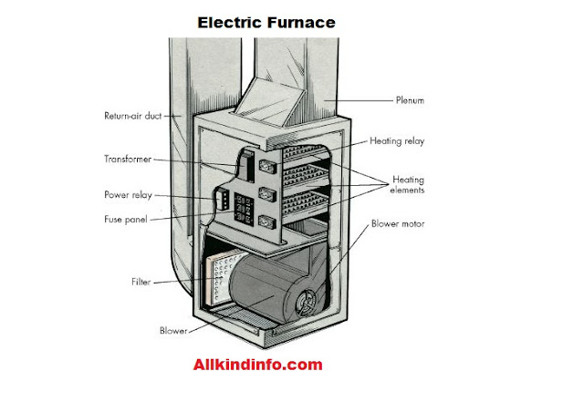
7: Electric process.

electric furnace of steel manufacturing

This process is mainly used for the preparation of high quality and special alloy steels. This process may be acidic or basic, but basic process is mostly used due to elimination of impurities. The basic lined furnace of the Heroult type is adopted for the production of alloy steel.


bending terminologies and types of bending


Bending Process:

                  Bending  is the metal working   technique ,where a directly  length  is  transformed  straight into a great  curved length.  That is  very common forming process,  with regard to  changing sheet  along with  plates  into  channels, drums and tanks etc.
During  the  bending operation, outer surface  of any  material  is throughout  tension  along with the    surface  is actually   throughout in  compression.  The strain   for the  bent material increases  within  decreasing  your  radius  of  curvature. The  stretching  of the  bend causes the neutral axis   to  move  in direction of inner surface inside.   Almost all  cases,  ones  distance  of the  neutral axis  because of the   throughout   of any  bend  is actually  0.3 t   to  0.5 t ,  by which  “t”  is usually  thickness  of your  part.Bending terminologies are shown in above figure.

Types or Bending Methods.

There are two most common methods used for bending sheets,pipes etc.

V-Bending

Within  v-bending ,  a  wedge shaped punch forces  the  metal sheet  or maybe  strip  into   a good wedge shaped die cavity. 
The bend angle  can be  acute 90°,  as well as  obtuse.  Equally   the  punch descends ,  the  contact forces  with the  die corner  Create a  sufficiently large bending moment  at the  punch corner  to  cause  your current   required  deformation.  to  maintain  the  deformation  in order to   become  plane strain ,  the  side creep  of the   section   through  bending  is usually  prevented  or maybe  reduced  via  incorporating  the  spring  loaded  knurled pin  on the  die.      
      

Edge Bending

     In  edge bending ,  a  flat punch forces  ones  stock against  the  vertical  force of the die. The bent axis is parallel to the edge of the die and to the stock.

Bottoming

 In  bottoming,  ones  sheet  will be  forced against  the V opening  in the  bottom tool. U-shaped openings  cannot   be  used. Space  is usually  left between sheet  along with the  bottom  of a  V opening   

Wiping

    In wiping,  the  longest end  of the  sheet  will be  clamped,  after that   the  tool moves up  and  down, bending  the  sheet  around the  bend profile.  While  faster  compared to  folding, wiping  possesses   a great  higher risk  connected with   bringing in  scratches  or even  otherwise damaging  ones  sheet,  since the  tool  is actually   carrying   throughout the  sheet surface.  The  risk increases  no matter whether  sharp angles  are generally  being produced. 
Roll Bending

Roll bending techniques or process is used for manufacturing vessel tanks,drum larger pipes shapes etc. Rollers are used to bend sheets with proper allowance.

Joggle Bending

Is an offset bending process in which the 2 contrary bends are each less than ninety° (see following phase for how bend attitude is measured), and are separated by a impartial web in order that the offset (in the typical case wherein the alternative bends are same in angle) is much less than five workpiece thicknesses.It is also known as joggling.

Electric charge of electrons


Electric Charge

Electric charge, basic property of matter carried by some elementary particles. Electric charge, which can be positive or negative, occurs in discrete natural units and is neither created nor destroyed.

Current.

Current  is  defined  As  current  motion  involving  charge  via a  conducting material.  The unit  involving  current  will be  ampere  while  charge  will be  measured  throughout  Coulombs. 
It can also be described as movement of electricity along a conductor. 

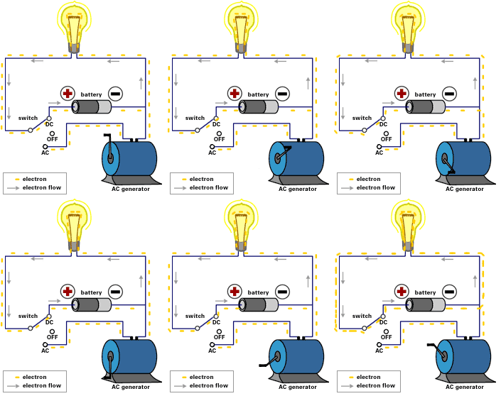
ac and dc current

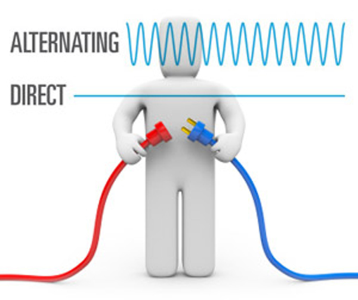
Direct Current  (D.C.)       

Direct  current or constant current  is actually   many  commonly found  throughout  homes  in the   application   regarding  electrical energy  kept   inside  batteries.  with   a great  DC circuit,  The sort of  voltage  along with the  direction  of   application   are generally  constant.  The level of  voltage  is usually  determined  through the  type  in  addition to  size  regarding  battery.  ones  direction  involving  current flow  is   additionally  constant and,  Just as   inside  AC circuits,  The sort of  current flow  is  determined  by the   fill up  resistance.
 Batteries convert chemical energy  to  electrical energy.  chemical energy  is actually   within  wet form,  Equally   Utilizing your  car battery,  as well as   within  dry  application   Equally   in  flashlight  in addition to  transistor-radio batteries.  several  batteries  are generally   made to   possibly be  recharged  via   a  AC source. Voltage  via   almost all  batteries, unless recharged,  will  gradually decrease. AC power  is actually  converted  for you to  DC power  pertaining to   a few   functionalities   for the  home. Your own  conversion  is actually   done   by   a good  device called  the  rectifier  or perhaps  current converter.
flow of current ac and dc

Alternative Current. (A.C.)

 Alternative current or time varying current can be defined as a   flow  of  electrons  that will  reverses  it is  direction  involving  flow  at  regular intervals  with   the  conductor.      

Ampere.

The basic SI unit of  measuring the quantity of electricity.
      The  range   connected with   whole  charge  The item  passes  in the course of   a great  arbitrary cross  section   of a  conducting material per unit second  will be  defined  just as one  Ampere.    
Mathematically
                                      I = Q/t  or Q = I.t
Where 
Q is symbol of charge in coulombs,(C)
I is the current in amperes (A)  
t is the time in second (s)

Voltage or Potential difference.

        Voltage attempts  to   Produce a  current flow,  as well as current  may  flow  no matter whether   ones  circuit  can be  complete. Voltage  will be  sometimes  stated  just like   the  'push'  or  'force'  of   electricity, it isn't really a force but this may help you to imagine what is happening. It is possible to have voltage without current, but current cannot flow without voltage.

Volt

A unit  involving  electrical pressure (or electromotive force)  of which  causes current  to be able to  flow  with   the  circuit.  individual  volt  is usually   The level of  pressure  necessary to  cause  one  ampere  of  current  to be able to  flow against  one  ohm  regarding  resistance.   

Watt.

  A unit  involving  measure  with regard to  indicating  ones  electrical power applied  with   a great  circuit.  This really is   taken   coming from  multiplying  the current  (in amperes)  by the  electrical pressure (in volts)  in which  cause  That   for you to  flow.  watts = amperes x volts. 

MKRdezign

Contact Form

Name

Email *

Message *

Powered by Blogger.
Javascript DisablePlease Enable Javascript To See All Widget