April 2020

1: Absolute Coordinate System

This is the basic system of the drafting used in Autocad. At the main screen of the graphical window, UCS icon is the most important element of this area. UCS stands for User coordinate system and in 2d (2 dimensional) two axis use for drafting. X-axis for horizontal and Y -axis for vertical lines. In 3d (3 dimensional) Z-axis is used for opposite axis against x and y axis.For using absolute coordinate system first you have to know that the origin point or source point which have the value of 0,0 for both x and y axis. First zero is the value of x and after comma the second zero is the value of the y. Most important rule of this system is the direction of the axis. 
In this system if you provide the value of x before comma, horizontal line will be draw and if you provide the second value (y) after the comma, vertical line will be draw. Both time if you draw straight line either in horizontal or vertical one value will be zero, only  when you draw the line in the x or y-axis.This system is only for 2004 Version and previous versions.
 Following figures are examples using absolute coordinate system.
absolute coordinate system autocad

2: Relative Coordinate System

This system is more flexible than absolute coordinate system, due to neglecting the origin point. Just pick any point of the drawing area and start your drawing. This first point will be your origin or source point. In this system neglecting the origin point, @ is added in the command line to provide the values. To understand the directions for x and y axis follow the figure.

relative coordinate system autocad

3: Polar Coordinate System.

Polar coordinate system used in autocad for angular/diagonal values. For Straight lines values for angles will be 0 and 180 for x axis. For straight lines values for angles will be 90 and 270 for y axis. To provide the angles the symbol of less than < is used. In this system only one value is given and angle is provide for direction. This system is very important to draw complex drawings.
To understand how to draw the angles follow the figure.
polar coordinate system autocad

4: Direct Entry Method System

This is the most common and easiest system used for drafting in Autocad. Values are provided through keyboard and direction is guided through the keyboard.

About autocad and screen introduction
Auto Cad is a unique software used for drafting. Cad is abbreviation of Computer aided design. This software is design and developed by American Company "Autodesk". Its first version was released in 1982.

Graphical Window - Screen Environment


1: Title Bar
Top bar of the screen of any software is called title bar. It consists of three common tab like close,maximize and minimize.
2: Menu Bar / Drop down List
It consists of Menu and is placed down the title bar. It belongs to the fundamentals of the autocad software.
3: Standard Tool Bar
It is the most common tool bar of every software which have the options like saving,cutting, copping and pasting of the files.
4: Object Property Tool Bar
This bar is related to the object properties like creating layers,changing the color etc of the object.
5: Modify Tool Bar
It is used to change the Drawing elements.
6: Draw Tool Bar
It is the most basic bar of the autocad used to draw primary units. Modify and Draw tool bar are placed in the left sides but you can change there positions.
7: Object snap Tool Bar
This tool bar is basically use to snap the object from the edges,center of the line and snap the round shapes from its center point.
8: Dimension Tool Bar
 This bar is used to Take the dimension of the object or drawings.Both object snap and dimension tool bars are situated at the right side of the graphical window.
9: Drawing Area
The main screen of making a drawing is called drawing area.Its colors are different according the version of the software. In 2004 version its color is black and in 2007 version its color is gray, but you can change its color as well. It consists of Cross Hair cursor and UCS (user coordinate system) icon.
10: Modify and layout tabs
These tab are placed with the horizontal scroll bar, used to plot the drawing.
11; Command Prompt
Its the most important and back bone element of the graphical window. Many  People do not follow the instructions shown in this prompt. Carefully follow step by step after entering the commands.
12: Status Bar
This bar indicates the positions of the all axis such as x for horizontal, y for vertical and z for 3d.
Status bar also have supporting tabs like snap,ortho,grid and polar etc tabs, which are helpful for creating smooth drawings.


component of machine design

Following are the general considerations in designing a machine component. 

Work facilities

Working environment plays a key role to design a machine component. A designer must familiar to workshop and work facilities. It is necessary to plan and supervise the workshop operations and to design method regarding to forging,casting and forming. 

Assembling

Every machine consists of components or parts and should be assembled as a unit before it can function. Large units must often be assembled in the workshop and then to be transfer to their servicing place.The final location is very important and the designer must knows the exact location and the local facilities for erection.

Kinematics.

Motion of the parts may be
(i) Rectilinear motion which includes unidirectional and reciprocating.
(ii) Curvilinear motion which includes oscillatory , rotary and simple harmonic.
(iii) constant velocity and constant or variable acceleration.
Successful operations contain simple arrangement of parts which will give the motion.

Friction

There is always loss of power due to frictional resistance and it must not forget that friction of starting is higher than friction at running. To overcome this failure appropriate lubrication is very important. Consider to matter of lubrication of all surfaces which move in contact with others, whether in rotating or sliding.

Cost of construction

Manufacturing a component should be smooth, easy and its overall cost should be minimum. So the cost of construction is very important asset to build or manufacture a component.

Part's Size

Form and size of the part are based on judgement. Either the part is small but it may be checked that the stresses induced in the designed cross-section are reasonably safe. To design any machine component or part for form or size, it is essential to know the forces which the part must sustain. Designer must know the suddenly applied or shock/impact load which may cause the failure.

Safety measures.

Some machines are very dangerous to operate, typically those which are speed ed up to insure production at a maximum rate. So safety measures must be follow to avoid accidents.

Stress and load.

The load, on a machine parts may act in different ways, due to which the internal stresses are set up. These stresses are like compressive,bearing,torsional and bending stressess etc.

Quantity

The number of components or machines to be manufactured affects the design in many ways. 

Economy Features.

In designing the operating  features of the machine should be carefully studied. The starting,controlling and stopping levers should be located on the basis of convenient handling.Replacement of other parts are should be located in easy mounting positions.

Material Selection

It is important that a designer should have a thorough knowledge of material's properties and their behavior under working conditions. Important features of material are strength, durability and flexibility etc. ( for more read the article in metallurgy)
or click the following link for material properties.

Trajectory method to calculate discharge of tube well and pipe outlet

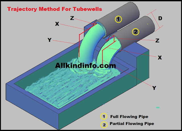
This technique is used to measure the discharge or flow for tube well or pipe sections. It is very simple and easy method to measure. It has basic three essential requirements for discharge determination.
Inside diameter of the pipe
Measurement of X-coordinate of flow ( horizontal distance measured from the end of the pipe)
Measurement of Y-coordinate of flow (vertical distance measured down from the horizontal point to the top of the water jet.)

Case A: for full flowing Pipe

tube well trajectory formula for flow


  Q = 0.0174 D X / Y
Where 
  Q = lps (liter per second)
  D = Inside diameter of the pipe (in centimeter)
  X = X-coordinate (cm)
  Y = Y-coordinate (cm)

Case B : for Partial FLowing Pipe

tube well trajectory formula for flow case 2

Where 
  Q = lps (liter per second)
  a = Area of jet
  A = Area of Pipe
  D = Inside diameter of the pipe (in centimeter)
  X = X-coordinate (cm)
  Y = Y-coordinate (cm)


drilling jigs types

Drilling jigs are classified into following types.
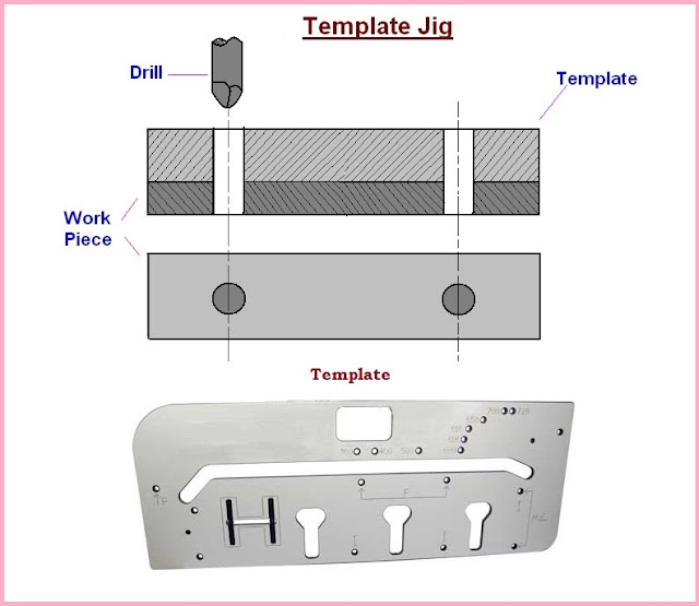
1: Template Jig
This is the  most simple in shape and easy to operate drilling jig. It can be used to drill many holes in the plate using a simple template plate..This type of jig is only useful when same work pieces are to be manufactured, other wise template can not be used to drill other work pieces.
template jig

2 : Plate Type Jig
This is the modified type of the template jig.Guide pins or bushes are used to guide the Drill. Work piece can be clamped through plates and holes can easily drilled.The plate jig is placed in such a way that accurate spaced  holes with their position can be created.
plate type drilling jig

3: Channel Jig
This type of jig have a channel. Work piece is clamped in the channel housing and fitted through the knob by screw fastening. Drilling operation can be performed through drill bushes.
channel jig

4 : Open Type Jig
This is also simple in construction and easy to operate. In this type the work piece is fitted on the top of the jig and clamped through nuts and bolts.
open type jig

5: Leaf Jig
This type of jig is same to the open type jig.The difference between the open type jig is only the top plate, which is placed to swing about a fulcrum point. In this type of drilling jig the work holding and loading/unloading of the work piece is very smooth and easy.Drill bushes are fitted into the leaf plate and guide the drill. This is also called latch or lid jig.
leaf latch lid jig

6: Box Type Jig
This is very special type of jig. When many holes from different sides are required, box type jig is used. Feet are provide to the jig to position the jig on the machine table. Top side of the jig is same as leaf type. Work piece is held in such a way that it created a box, so that it is called box type jig. Typical Box type jig is shown in the figure.
box type drilling jig


body types of jig and fixtures

Different elements of jigs and fixture are commonly used in the workshop and their uses and functions are as follows.

1 : Body

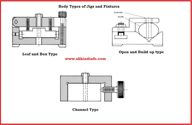
Material of jig body is made from cast iron manufactured through casting or fabrication operations. Body slabs and bars are fabricated by welding and then heat treated to decrease the stresses. Its main function is to support the work piece and hold the job.Different body types of jigs and fixtures are as follows.

(i) Plane Type Body

The most simplest form of body is called plane type body. When holes to be drilled in a simple way this type of body could be used. Drilling operation can be performed without or with the guide bushes.

(ii) Channel Type Body

This type of body contains a channel or more than two channels. Channel are made from steel and Cast Iron materials. 

(iii) Box Type Body

When many holes are required from different sides. Template plates can be used to drill from any plane.One side of the box is mounted with a lid, which is helpful for loading and unloading the job.

(iv) Built Up Type Body

Dowels, screws and locating pins are used in this type of body. Material of this body is a standard steel. Blocks are used to locate and position the job.

(v) Leaf Type Body

This is the most advanced and modified type of body. A fulcrum type lid is adjusted on the top of the body.It is used in case of measured large work pieces where it may necessary to hold the whole component in the jig. 

2: Locating Devices.

Different types of pins are used to locate the component in the jigs and fixtures body.  These pins are made from hardened steel. Shank or neck of the pin is press fitted into the jigs and fixtures body.Various types of locating pins are.

(i) Support Locating Pins

These are also called rest pins, which are used to adjust the work piece. Support locating pins have two kinds. First type is called fixed type, which are used to locate the face either round, curved or flat. Spherical or round head insure stable locating.Second type of pins are adjustable type, which are used where dimension of work piece can vary. These are mostly used in forging,sand casting.
support locating pins adjustable and fixed type

(ii) Locating Pins

When Finished holes or reaming is required then these pin are used. These pin are also used to locate the work piece as well. Conical and cylindrical types of locating pins are used in the work shop.
locating pins types
jigs locating pins

(iii) Jack Pins

These pins are also called spring pins. Purpose of these pins are to locate the job whose length is subject to variation. Spring allows the compression and locate the work piece easily. Locking screw type of jack pin is more secure when job is adjusted and then pin can lock whole face of the work piece.
jack pins
)

Reamer and there types

Definition of reamer
A reamer is a turning cutting apparatus by and large of round and hollow shape which is utilized to augment and complete openings to exact measurements to already formed hole. It is a multiple edge cutting edges having the front line on its periphery.
Parts of Reamer.
1.     Fluted section                               2.  Neck                                             3. Shank
The fluted part comprises of chamfer, beginning decrease, sizing section an back taper length. Chamfer length or bevel lead protects legitimate and simple section of the reamer into the gap. The principle cutting activity of reamer is finished by beginning decrease, the estimating segment and to direct the reamers furthermore smooth or size the hole.The back taper reduces friction between reamers and the whole surface.

Types of Reamers
1: Hand Reamer
These reamers are worked by hand with a tap wrench fitted on the succession of the reamer. The work is hold in a vice. The flutes might be straight or helical. Shank is straight with a square tang for the wrench.
2: Machine Reamer
It is same as hand reamer but the shank is different (tapered) 
3: Chucking Reamer
These are machine reamers with shorter woodwinds. These might be both of the sort known as rose reamers or fluted reamers. These are utilizing for roughing cutting.
4: Shell Reamer
Solid reamers (up to around 10 mm radius generally made of Hss) to lessen the expense of bigger reamers the cutting segment is made as partitioned shell which are mounted on standard shanks made of lower cost steel. These reamers are however don't extremely inflexible and exact embedded tooth or plates in shells in further lessened the expense of reamers can tip with established carbides.
5: Tapered Reamer
These reamers are used for cutting tapered holes and finish taper bores such as pulleys,collars and shafts etc.
6: Adjustable Reamer
In these reamers separate cutting edges are embedded in the grooves gave in the body of the reamer. The sharp edges can be moved or down of the reamer.
7: Expanding Reamer
These reamers permit slight increment in their size to take wear and finish an additional measure of material. For this the body of the reamers is bored tapered is slitted. A tapered plug goes through the opening end is worked by a screw and acts like an ex pander.
8: Fluting Reamer
There the holder are not inflexible but rather are fluting this allows the reamer. To stream the already made gap actually and without controlled bringing about a superior hole.


transformer is a static or stationery apparatus which transformed electric power from one circuit (same frequency) to another circuit. It can raise or fall down the voltage in a circuit but with a regarding to increase or decrease in the current.
The physical basis of transformer is mutual induction between two circuits connected by a common flux. It consists of two inductive coils  which are electrically separated but magnetically connected by a path of low reluctance. The two coils posses high mutual inductance.
If one coil is linked to a source of alternating voltage, an alternative flux is set up in the laminated core. Most of which is connected with the other coil in which it raise mutually induced e.m.f. If the secondary coil circuit is shut down, a current flow in it and so electric energy is converted from
the first coil to second coil. The first coil , in which electric energy is fed from the a.c. supply , it is called primary winding and the other which drawn out the energy is called secondary winding.
In conclusion we can say the transformer is a device which
(a) transfers electric power from one circuit to another.
(b) it does so without a change of frequency.
(c) it accomplishes this by electromagnetic induction
(d) When two electric circuits are in mutual inductive influence of each other

Basic Theory of a Transformer
Let's assume you make them wind which is supplied by a alternative electrical source. The alternative current through the winding creates a consistently changing flux or alternative flux that encompasses the winding. In the event that some other winding is conveyed closer to the past one, clearly some segment of this flux will interface with the second. As this flux is constantly altering in its amplitude and direction, there must be an adjustment in flux linkage in the second winding or coil. As indicated by Faraday's law of electromagnetic induction, there must be an EMF prompted in the second. In that the circuit of the later winding is shut, there must be a present moving through it. This is the easiest type of electrical force transformer and this is the most essential of working rule of transformer. For better understanding, we are attempting to rehash the above clarification in a more short manner here. At whatever point we apply exchanging current to an electric coil, there will be a rotating flux encompassing that loop. Presently in the event that we bring another loop close to the first, there will be a rotating flux linkage with that second curl. As the flux is exchanging, there will be clearly a rate of progress in flux linkage concerning time in the second loop. Actually emf will be prompted in it according to Faraday's law of electromagnetic impelling.

Basics of Forex Trade
The Forex business sector is the place where banks, organizations, governments, speculators and merchants come to trade.The Forex business sector is additionally alluded to as the 'Fx market', 'Currency market'or'foreign trade currency business sector'  is the biggest and most fluid business sector on the planet with a normal day by day turnover of $4 trillion. The Fx business sector is open 24 hours a day, 5 days a week with the most vital world exchanging focuses being situated in London, New York, Tokyo, Zurich, Frankfurt, Hong Kong, Singapore, Paris, and Sydney. It ought to be noticed that there is no focal commercial center for the Forex market; exchanging is rather said to be directed 'over the counter'; dislike stocks where there is a focal commercial center with all requests handled like the NYSE. Forex is an item cited by all the real banks, and not all banks will have precisely the same. Presently, the broker take all propositions encourages from the distinctive banks and the quotes we see from our dealer are an estimated normal of them. The specialist is viably executing the exchange and taking the opposite side of it… they 'make the business sector' for you. When you purchase a money combine… your specialist is offering it to you, not 'another broker'.
What is Forex Trading
Forex exchanging as it identifies with retail dealers (like you and I) is the hypothesis on the cost of one currency against another. For instance, on the off chance that you think the euro is going to ascend against the U.S. dollar, you can purchase the EURUSD cash combine low and after that (ideally) offer it at a higher cost to make a benefit. Obviously, on the off chance that you purchase the euro against the dollar (EURUSD), and the U.S. dollar reinforces, you will then be in a losing position. In this way, it's critical to know about the danger required in exchanging Forex, and not just the prize.
Brief History of Forex Trade
In 1876, something many refer to as the gold trade standard was actualized. Fundamentally it said that all paper cash must be upheld by strong gold; the thought here was to balance out world monetary standards by pegging them to the cost of gold. It was a smart thought in principle, yet as a general rule it made blast bust examples which at last prompted the death of the best quality level.

The highest quality level was dropped around the start of World War 2 as significant European nations did not have enough gold to bolster all the coin they were printing to pay for substantial military activities. Despite the fact that the best quality level was eventually dropped, the valuable metal never lost its spot as a definitive type of fiscal worth.


The world then chose to have altered trade rates that brought about the U.S. dollar being the essential store cash and that it would be the main coin supported by gold, this is known as the 'Bretton Woods System' and it happened in 1944 (I know you super eager to realize that). In 1971 the U.S. pronounced that it would no more trade gold for U.S. dollars that were held in outside stores, this denoted the end of the Bretton Woods System.

It was this separate of the Bretton Woods System that at last prompted the for the most part worldwide acknowledgment of gliding remote trade rates in 1976. This was adequately the "birth" of the current remote cash trade market, despite the fact that it didn't turn out to be broadly electronically exchanged until about the mid 1990s.

It is very important command in autocad. It is helpful to make complicated drawings such as gears, sprakuts, pulleys etc. To use this command you just have to learn its basics. In autocad it has two types.
Rectangular Array.
It is use to arrange rectangular object formation in quick time. After putting your command in the command prompt you just have to pick rectangular array. for further detail please check the drawing.


Polar Array
This command in autocad is most helpful for the designers and draftsmen. For Polar array you need to put right center points and paths. Number of object stands for total rotational objects. Gears, Sprakuts, Pulleys, Flanges bores. etc and other mechanical parts are forms in this command.


Copy and Move Commands
Common commands used in all programs. In Auto cad it is also used to move or copy the objects from one position to another position.
Rotate Command.
This command in autocad used to rotate the objects, lines, patterns to one direction to another direction. For Rotate an object you have to know about the angles and there positions.
Xplode.
This command is used to break one unit object. Circles, Polygons, Rectangles are the one unit objects.
Fillet and chamfer Commands
Round edges and chamfer edges on the patterns and drawings, these command are used. for fillet command type your radius and select your drawings corners.

MKRdezign

Contact Form

Name

Email *

Message *

Powered by Blogger.
Javascript DisablePlease Enable Javascript To See All Widget