April 2016

flow measurement through trapezoidal

The basic formula for channel capacity is
Q = A x V
Manning's formula for velocity is   
By combining these two formulas , channel capacity or quantity of flow can be determine by 
where              
Q = Quantity of flow in cubic meters per second                     
V = Mean Velocity in meters per second                                  
A = Flow area in square meters                                                
P =  Wetted perimeter in meters                                               
R = Hydraulic radius in meters = A/P                                     
S = Slope or energy gradient in meters drop per meter length
n = Roughness coefficient                                                       
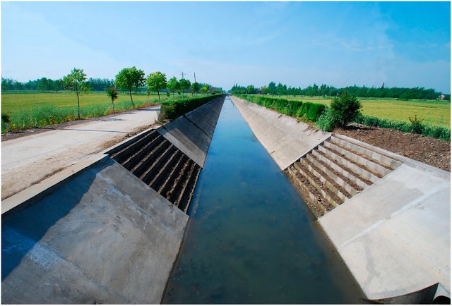
Trapezoidal Watercourse/canal or Channel
flow quantity through trapezoidal channel

Flow measurement or hydraulic formulas are used to measure the discharge/volume of water through canals,irrigation channels,watercourses,drain lines etc. Following is the brief descripion used to calculate the flow measurement or discharge of the trapezoidal sectioned channel.
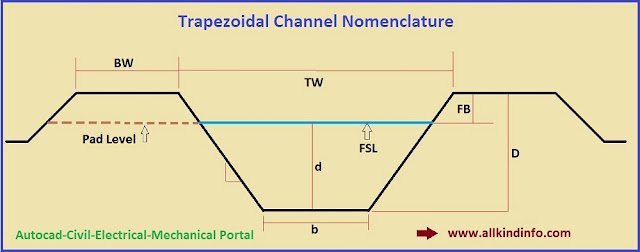
b = bottom width                                                                              d = flow depth              
B = width at water surface = b + ( 2 x z x d )                                  FB = Free board
D = Total depth of channel = d + FB                                               BW = Bank width
Z = Side slope, ( Such as 1: 1 - 1.5 : 1  & 2 : 1)                              FSL = Full supply level
TW = total width of the ditch = b + ( 2 x Z x D)
So formula for trapezoidal channel flow quantity is
 A = b x d + Z x d²
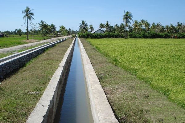
Rectangular Watercourse/canal or channel
flow measurement through rectangular channels

flow measurement through rectangular watercourse

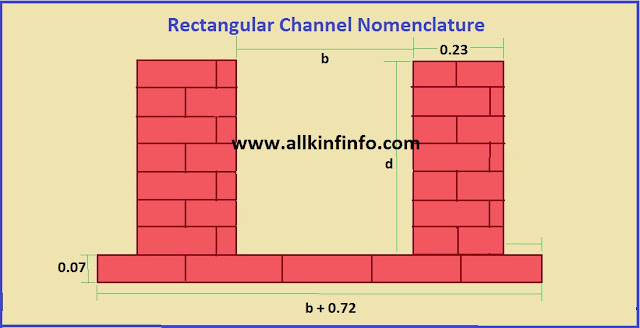
A = b x d
where b is the width of the channel and d is the depth of the channels.


stones and their types

Building stone is gotten by taking rock from the earth and decreasing it to the required shapes and sizes for development. It is a characteristic, lavishly various material that can shift incredibly in its science, structure, physical properties, and appearance. Geographically, stone can be classified into three sorts as indicated by how it was formed.
  •  Igneous rock will be rock that was stored in a liquid state. 
  • Sedimentary rock will be rock that was saved by the activity of water and wind.
  • Metamorphic rock was some time ago either volcanic or sedimentary rock. Consequently, its properties were changed by warmth and weight.
Granite Group: 
granite stone group

Stone is the igneous rock most normally quarried for development in North America. It is a mosaic of mineral gems, mainly feldspar and quartz (silica), and can be gotten in a scope of hues that incorporates dim, dark, pink, red, chestnut, buff, and green.Granite rock is nonporous, hard, solid, and strong, the most almost perpetual of building stones, appropriate for use in contact with the ground or in areas where it is presented to extreme weathering. Its surface can be  finished in any of various compositions, including a mirror like shine. In North America, it is quarried predominantly in the East and the upper Midwest. Different stones are likewise foreign made from abroad, from Brazil, China, India, and Italy. Residential stones are classified as indicated by whether they are pre-grained, medium- grained, or coarse-grained. Prerequisites for rock measurement stone are depended in ASTM C615. 
Limestone Group
limestone engineering materials

Limestone is one of the two important sedimentary rock sorts utilized as a part of construction. It might be found in an strong stratified structure. It is quarried all through North America, with significant quarries for large dimension stone found in Missouri and Indiana. France, Germany, Italy, 
Spain, Portugal, and Croatia are significant suppliers of imported limestone. 
Necessities for limestone measurement
stone are determined in ASTM C568. Limestone might be made either out of calcium carbonate or of a blend of calcium and magnesium carbonates. Both sorts were shaped long prior from the skeletons or shells of marine living beings.colors range from practically white through dark and buff to iron oxide red. Limestone is permeable and contains extensive groundwater (quarry sap) when quarried.  While still immersed with quarry sap, most lime stones are anything but difficult to work however are powerless to frost damage.

 In the wake of flavoring noticeable all around to dissipate the quarry sap, the stone gets to be harder and is safe frost damage. Some thick lime stones can be cleaned (and might be delegated marbles), however most are delivered with fluctuating degrees of surface composition. 
Quartz-Based Dimension Stone Group
Sandstone is the second major sedimentary rock sort utilized as a part of building construction. Like limestone, it might be found in either an unequivocally stratified structure or as more homogeneous freestone. Sandstone was shaped in old times from stores of quartz sand (silicon dioxide).
Its shading and physical properties shift  with the material that concretes the sand particles, which may comprise of silica, carbonates of lime, or iron oxide. Sandstone is quarried essentially in New York, Ohio, and Pennsylvania. Two of its more well known structures are brownstone, broadly utilized as a part of divider development, and blue stone, an exceptionally stratified, strong stone and durable.
Slate Group
slate stones group

Slate is one of the two trans formative stone gatherings used in construction. Slate was shaped from clay. It is a thick, hard stone with firmly separated planes of cleavage, along which it is effortlessly part into sheets, making it helpful for clearing stones, rooftop shingles, and thin divider facings. It is quarried in Vermont, Virginia, New York, Pennsylvania, and parts of Canada, in an assortment of hues including dark, dim, purple, blue, green, and red. China and India are the biggest outside suppliers of slate to North America, with Italy, the United Kingdom, and Spain.
Marble Group
marble stones

Marble is the second of the major changeable rock groups. In its actual geologic structure it is a recrystallized type of limestone. It is effortlessly cut and cleaned and happens in white, dark, and about each shading, frequently with wonderful examples of veining. The marbles utilized as a part of North America come from Alabama, Tennessee, Vermont, Georgia, Missouri, and Canada. Marbles are likewise foreign made to this landmass from everywhere throughout the world, essentially from Turkey, Lebanon, Mexico, Italy, China, and France. The physical properties and appearance of marble differ significantly, contingent upon the science of the first limestone from which it was framed and, much all the more in this way, on the procedures by which it was transformed.

solar power system

The vitality from the sun reaching on  the earth every day ranges from around 600 Btu (British Thermal Unit)/square feet for Northern Europe to around 2000 Btu/square feet for parched locales close to the equator. More vitality from sun strikes the earth in one hour than all vitality expended on the planet in a year! A summer day's sun with full swing provides a  square, meter of area with a power include very nearly a kilowatt. One may ask why sun oriented vitality has not supplanted the customary vitality sources, not even a huge division. So there are unquestionably  more advantages and a few disadvantages of solar power system.
Advantages of Solar Power.
No Pollution and Global warming friendly.
Solar Panels does not create any pollution while producing electricity. Global warming  threatens  the survival of human culture, and in addition the survival of incalculable species. Fortunately, decades (or even hundreds of years) of exploration have prompted effective sun powered board frameworks that make power without creating a worldwide temperature alteration contamination. Sunlight based Solar power is presently plainly a standout among the most critical answer for the global warming.
Cost Comparison
Once time installed the expense of power generation is low however the expense of creating sun oriented cells are high. What's more, in the remote regions the establishment expense will be relatively low. Sunlight based boards can be set up in the house rooftop. So there is no necessity of discovering spaces.The normal 20-year investment funds for Americans who went solar powered in 2011 were anticipated to be somewhat over $20,000. In the crowded conditions of New York, California, and Florida, the anticipated investment funds were over $30,000. In the sunny yet costly heaven known as Hawaii, the anticipated funds were about $65,000!. So we can say that solar system is best for household,farmers and as well as for industries.
Availability and Reliability 
Most countries of the world have the sun rays and availability of the solar power generation is very easy. All across the world, we know precisely when sun will rise and set each day of the year. While mists might be somewhat less unsurprising, we do likewise have genuinely great regular and day by day projections for the measure of daylight that will be gotten in various areas. All things considered, this makes solar power to a great reliable source of energy.

Energy independence and zero dependence of fuels.
Solar power provides easy energy independence to every one. One time installation and you are free and zero dependent of other sources of energies. The reliance on the fossil energizes can be lessened an awesome arrangement. In one day the sun based vitality falling on India alone is more prominent than the vitality in their present yearly coal utilization.
solar system advantages

Creating of new Jobs
Due to new innovation, Solar Power system creates new job opportunities for unemployed skilled workers.In Pakistan there are many several solar power projects creates a lots of jobs. Solar power panel plates companies and other renewable energy firms hires and facilitates the skilled persons.  
No Transportation Charges.
As We said that it has only once time installation charges. When you compare other energy resources it has no transportation charges.
Disadvantages of Solar Power system
Solar power system has very rare disadvantages like covering a lots of space (For large energy production), energy storage is also a disadvantage.

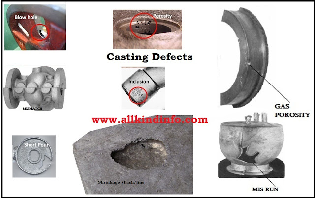
sand casting defects, porosity,missrun,shrinkage

Although casting provide cheap and easy manufacturing machine parts, but there are some defects found in the casting procedure. These casting defects are due to pattern , casting equipment like mold box, molten material and cores. Follows are the some defects and their detail.
1 : Blow Hole
It is smooth depression  on the external surface of the casting object. It is also termed as sand blow.
2 : Mismatch or Mold shift
When bottom and top mold plates are mismatched with each other, it causes mold shift defect in the work piece. The object does not equal join with each other.
3 : Short Pour
Casting inadequate because of not filling the mold. This is a doltish trap which we as a whole do-bring about deficient metal in the ladle.
4 : Porosity /Steam Gas Porosity
This deformity as a rule appears as round openings like swiss cheese, simply under the adapt surface of the throwing and becomes exposed when light machining. The cause is a wet ladle, where the ladle covering was not appropriately and altogether dried. In compelling cases the metal will kick and bubble in the ladle. The act of pigging the metal in a wet ladle and refilling it with the trusts that the pigged metal wrapped up the ladle is sheer fully.
5 : Cold Shut or Miss run
These happens when the mold pit is not totally filled by the liquid and inadequate material or metal.
6 : Swell
It is an extension of the mold depression by liquid metal weight bringing about restricted or general augmentation of the casting.
7 : Fins or Flash
These are meager projections of the metal not proposed as a piece of casting. These more often than not happens at the separating line of the mold.
8 : Sand Wash
It occurs near the gates as a rough spots or lumps on the casting work piece.
9 : Shrinkage
It is a split or breakage in the casting on the surface of the work piece, which results from un equal  withdrawal of the metal during hardening.
10 : Hot Tear
It is an inward or outside worn out spasmodically in the metal casting  coming about soon after the metal has cemented.
11 : Slag Holes
This defect is also known as honeycombing. These are smooth depression  on the outer surface of the casting.It occurs near the ingrates.
12 : Scabs
These are patches of sand on the outer surface of the casting work piece.
13 : Run-outs and Bust-outs
These grant seepage of the metal from the hole and result in inadequate casting.

14 : Buckle
A buckle is a long, genuinely shallow, broad, v depression  that happens in the surface of level castings. It reaches out in a genuinely straight line over the whole level surface. 

It results because of the sand expansion brought on by the heat of the metal, when the sand has inadequate hot distortion. It additionally comes about because of poor casting plan giving too extensive a level surface in the mold cavity. 
 15 : Bleeder
This fault is brought about by shaking the casting out too early when a part of it is still fluid. The area runs out leaving an imperfection. In great cases the whole focus segment will run out on the shake out man's feet.


3d Solid shapes in autocad

In Autocad 2007 version, exists with the name of Modeling tool bar and In Autocad 2004 version, it exists with the name of Solids. This tool bar has extra features to draw solid geometrical shapes in isometric or 3d. Follow the instructions and step by step procedure are as follows.

Step 1 : First add above mentioned tool bar regarding your autocad version. (Right click at the any tool bar on the autocad screen and click your desired tool bar.)

Step 2: Click on the south east tab from the view tool bar.

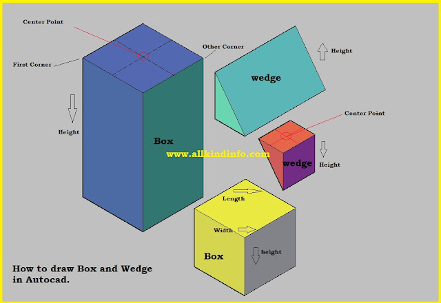
How to draw Box and Wedge.
3d box and wedge in autocad

1:Click on the box icon from the modeling tool bar.
2: Click first point (starting point) or enter c (for starting your shape from center).
3: Enter your desired rectangular dimension of length and width. You can enter your length and width amount by entering @ 100 , 50 where 100 will be your desired length and 50 will be width. If you enter one dimension it will create square.
4:  Now enter your desired height.
For Wedge draw as same as above mentioned. But you can change your height direction by the help of your mouse.
How to draw  Cone and Cylinder
3d cone and cylinder in autocad

1: Click any point on the drawing area for center point.
2: Provide Radius of the base circle and provide your desired height.
3: For 3P and 2P options follow the diagram,
4: If you want to draw an elliptical Cylinder or elliptical cone, after click the your desired icon enter e for base ellipse. Provide first axis and second axis dimensions and then enter your third elliptical dimension. After making your base ellipse provide your desired height.
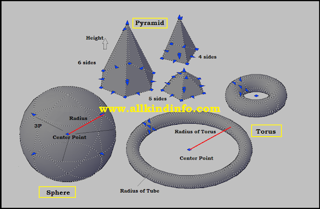
How to Draw Sphere.
1: Click any point for center point of the sphere.
2: Enter your radius or enter d for diameter and twice your dimension.
How to draw Torus.
torus,shpere and pyramid shapes in autocad

1: Click the center point to start your torus
2: Enter your desired dimension of radius (Radius of Torus)
3: Then enter your Torus tube's radius dimension.
How to draw Pyramid
1: Click any point to start your pyramid.
2: Enter your desired height of the pyramid.
If you enter e for edge at the start it will create your base from its edges. and if you enter s it asks how many sides are required.

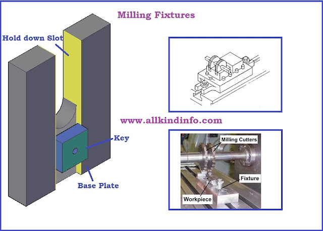
milling fixtures

Commonly, the jigs and fixtures devices found in a machine or workshop are for machining operations. Different operations, be that as it may, for example, assembley, layout, testing, and design, are additionally ranges where work holding devices are appropriate. There are numerous  varieties inside every broad arrangement, and numerous work holders are really combination of two or a greater amount of the orders.
Common Applications of Jigs and fixtures are as follows.
1: External Surface Machine Applications
Flat-Surface Machining
grinding fixtures

   • Milling fixtures
   • Surface-grinding fixtures
   • Planing fixtures
   • Shaping fixtures
Cylindrical-Surface Machining
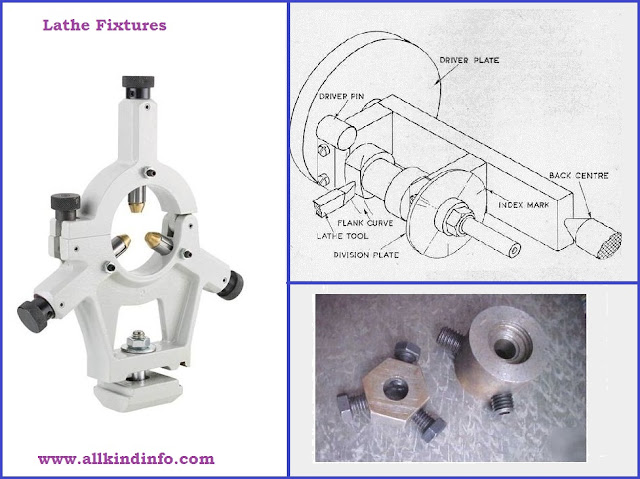
lathe fixtures

   • Lathe fixtures
   • Cylindrical-grinding fixtures
Irregular-Surface Machining
   • Band-sawing fixtures
   • External-broaching fixtures
2: Internal Surface Machine Applications

Cylindrical- and Irregular-Hole Machining
   • Drill jigs
   • Boring jigs
   • Electrical-discharge-machining fixtures
   • Punching fixtures
   • Internal-broaching fixtures
3: Non Machining Application Assembley
welding fixtures

   • Welding fixtures
   • Mechanical-assembly fixtures
     (Riveting, stapling, stitching, pinning, etc.)
   • Soldering fixtures
4: Inspection
   • Mechanical-inspection fixtures
   • Optical-inspection fixtures
   • Electronic-inspection fixtures
5: Finishing
   • Painting fixtures
   • Plating fixtures
   • Polishing fixtures
   • Lapping fixtures
   • Honing fixtures
6: Miscellaneous
   • Layout templates
   • Testing fixtures
   • Heat-treating fixtures
7: Modular Fixtures
modular fixtures

Modular fixtures accomplish a considerable lot of the benefits of a changeless device utilizing just a temporary setup.Modular work holding join thoughts and components of both lasting and temporary work holding to make reasonable yet-solid work holders.The essential point of interest of modular fixtures is that an apparatus with the advantages of lasting tooling (setup reduction, toughness, profitability upgrades, and precision) can be worked from an arrangement of standard segments.

formatting of multi line in autocad

Multi line 
This line is used to draw parallel two or more offset ed lines in autocad. Highway road center white line and yellow colored outer lines is the example of multi line. 
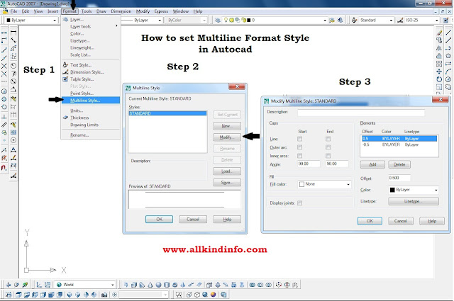
Formatting of Multi line
1: Click on the Format tab in menu bar
2: Click on the Multi line Style from the drop down list.
3: Click on the modify tab.
4: After clicking the modify tab another menu box will be appear.
There are three portions and there setting are as follows.
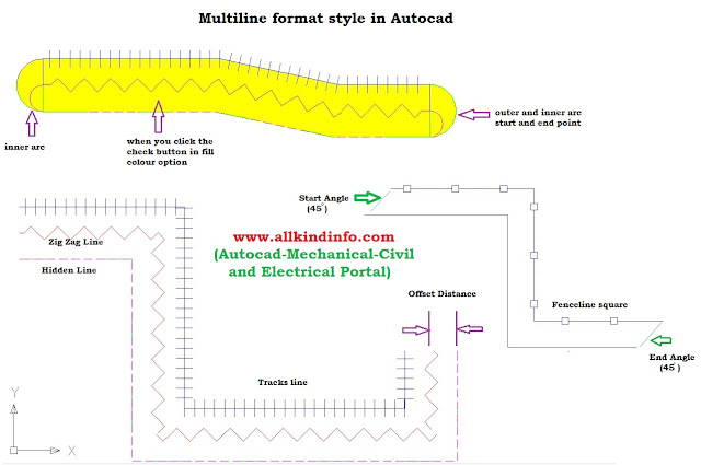
multi lines formatting

(a) Caps
In this portion there are six check buttons, which are used to format multi line start and end round fillets. If you check these buttons round fillets (round circles) will be apply.
Angle can be adjusted by entering the values (Such as 15,30,45,60 degrees etc). First value entry will be appear at the starting point and second value will be appear on the end point.
(b)Fill
This portion is for apply inside color in the multi line. Chose any color and select to apply. Gray color of road is the example.
(c) Elements
In this portion you can format line types, there colors and there offset distance (Parallel line distance). If you want to add more than two lines then click on the add button. 
multi line in autocad

How To Draw Multi line
Click on the draw tab in menu bar. Scroll down the mouse and pick the multi line and pick the start point and navigate your direction through mouse. Every time your formatting multi line will be set according to your format which was set in the formatting multi line style. To draw different multi line, click on the new tab and save the multi line format style.


Construction and ray lines in autocad

Line
The basic and most important element of drawing used in auto cad. Short key of line command is "L".
Every time you enter the short key of any command, follow the instructions in the command bar. When you press " L" in the command bar, message appear in the command bar " specify first point".
Click on any point at the drawing area. Navigate your direction through mouse and enter your required length or click any point. As we know basic definition of line is " the distance between two point is called line.In Auto cad 2004 or previous versions supporting lengths and angle does not appear when you navigate the line's direction.(It does not mean that they does not appear, such information if you want to check, appears on the status bar). In Auto cad 2007 and onward versions provide supporting lengths and angles.
Ray
Ray command is used for making horizontal and vertical lines which are used as a reference lines or extension lines.These lines are helpful to make object which are parallel to each other. If you are draftsman, there are so important to draw objects in first and third angle projection methods. Here you have to draw parallel object side,front and top views. To draw ray lines follow the given instructions.
Click on the draw menu, from drop down list select the ray command.
Specify start point. (provide the reference point from where ray line should start.)
Specify through point (provide direction and click from there)
Construction Line
Method to draw construction line is same with ray line, but construction line have both sides extension. These extend lines can be trim after completing the object. These lines are also can be drawn either in vertical or horizontal axis.(or you can draw in diagonal axis.)

reverberatory furnace and wrought iron

Cast Iron
Pig iron alongside scrap iron, coke and limestone is liquefied in a vertical furnace called cupola. Here likewise the carbon and different impurities introduce oxidize in nearness of a little measure of air, to shape slag. The liquid iron got from dome heater can be thrown into forms. It is, thus, known as cast iron. It comprises of 93-94% Ferrous, 2-4% carbon and a small amount of S, P, Si and Mn polluting influences. It is  hard and brittle. It is cast into covers of main holes, channel pipes, casings of machines etc.
Wrought Iron
The most purist form of iron is called wrought iron, which contains up to 99 % of iron and small amount of carbon with impurities such as sulfur , manganese, silicon and phosphorus.wrought iron is malleable, tough, gray and can be welded. It is mold able and has a sinewy structure because of the nearness of thin movies of slag between layers of pure iron. The nearness of slag makes it greatly extreme and safe towards rusting
Manufacturing Process
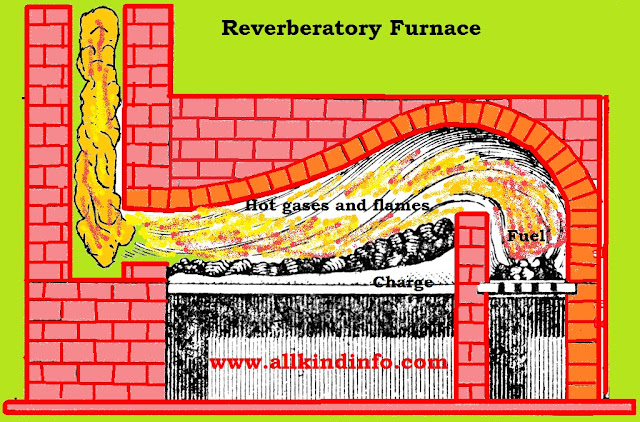
It is acquired from cast iron by evacuating the significant partition of its impurities influences by the surely understood puddling process.The cast iron alongside some scrap iron is warmed on the hearth of a reverberatory furnace lined with hematite. The hot gasses and flames reflected from the top of the heater falls upon the charge set on the hearth. The cast iron softens down and the liquid mass is blended or puddled at intervals by method for a long pole presented through a channel in the wall of the furnace.  The haematite supplies the oxygen required to oxidize the carbon, sulfur, silicon, manganese and phosphorus show in the cast iron. 
Chemical Reaction
Carbon and sulfur are oxidized to carbon dioxide and sulfur dioxide, individually. Silicon and manganese are oxidized to silica and manganese oxide, which join to frame manga-nous silicate.
3Si + 2Fe203 —* 3Si02 + 4Fe 3Mn + Fe203 —» 3MnO + 2Fe MnO + Si02 —» MnSi03
Slag Formation
As the contamination are dispensed with, the liquefying purpose of the metal ascents and iron gets to be pasty. The pasty mass is blended which frames "balls" or "blooms" which are elastic in composition because of a lot of slag. The balls are taken out from the heater and the slag is crushed out by crushing or hammering. At last, iron is moved into sheets or manufactured into bars.
Chemical Reaction

Phosphorus is oxidized to phosphorus pentoxide which forms ferric phosphate slag with haematite.
P205 + Fe203 —* 2FeP04


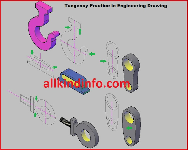
tangency exercises

Fig a :
Given an acute angle, it is required to obtain a circle of any given radius tangential to both its arms.
Method: Suppose the circle is to be drawn on the given dimension. Obtain lines known as loci parallel to diagonal and base lines.(given distance on figure is 3/4"). These lines intersect each other and provide a point where u can draw a circle tangent to both arms.
Fig b:
Given a circle, it is required to obtain circles tangential to its circumference.
Method : Draw three circles at given dimensions. Draw parallel locus (loci drawn in previous method) lines. Draw parallel circles at there tangents points.

Fig c :
Tangency  to  parallel circles tangents.
Method : Draw three parallel lines as drawn on the fig c. (Both horizontal and vertical lines.) Here you will get the circles center points. These circle will intersect each other at there tangency.
Fig d :
Given two circle which are not tangential , it is required to obtain two other of given rad. tangential to them externally.
Method : Draw horizontal and vertical center lines. Draw two circles with given length radius. Draw two circles arc respectively. then you will get small circle center points.
Fig e :
Obtain a circle which shall be tangential to the larger circle internally and to the smaller circle externally.
Fig f: 
Obtain circles tangential to the mid point of the straight vertical line.
Method : Draw a line perpendicular to the horizontal line. This horizontal line consist of the centers of the given radius circles.
Fig g :
Draw an ogee curve between two parallel straight lines.
Fig h-i-j
Draw fillets or rounds when the angles are acute(fig j) , right (fig h) and obtuse (fig i)
Method: The center of any circle tangential to the arms of an angle lies on the bisector of the angle. Therefore we may bisect the angle.
Common tangency practice in engineering drawing/machine parts is shown in fig.
tangency practice in machine parts


electric arc welding

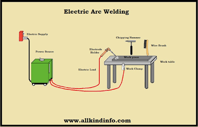
The arc welding is a type of fusion welding process in which the welding warmth is acquired from an electric curve struck between the work(or base metal) and a electrode. The temperature of the warmth created by the electric arc is near to 6000°C to 7000°C. Both the direct current (D.C) and alternate current(A.C) might be utilized for this welding, however the alternate current is favored for generally purposes.At the point when the work is associated with the positive terminal of the D.C welding machine and the negative terminal to a electrode holder, the welding set up is said to have straight polarity.  Then again, when work is associated with negative and the electrode to a positive terminal, then the welding set up is said to have reversed polarity . The straight polarity is ideal for a few welds while for different welds turned around reversed polarity  ought to be utilized.
Following are the two types of arc welding depending upon the type of electrode:
1: Shield Arc Welding
When the electrode rods with covering material of fluxing are used, this type will be called shield arc welding.
2: Non Shield Arc Welding
When a filler rod or electrode is used for welding, this method is called non shield arc welding.
Arc Welding Processes
how welding works

Various types of arc welding processes are commonly used in the workshop,there are as follows.
(i) Metal Arc Welding
The arc is produced between the metal and the work piece Metal electrode is melted through heat and joined the work piece. The temperature produced is upto 2700 degree centi grade.
(ii) Carbon Arc Welding.

In carbon arc welding, the welding heat is acquired from an electric arc between a carbon electrode and the work piece. In welding substantial plants, the extra metal is stored in the weld from a filler rod.
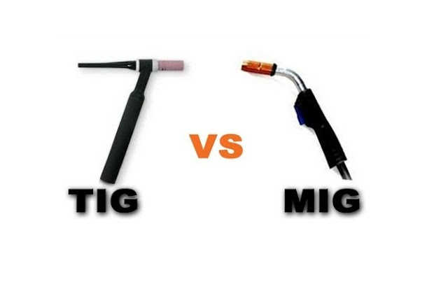
(iii) Metallic inert gas (MIG) arc welding
MIG (metal inert gas) welding

In MIG arc welding ,the electrode is consumable, the filler metal is saved by the arc which is totally encompassed by a inert gas.
(iv) Tungsten inert gas (TIG) arc welding
tungsten inert gas welding

In TIG arc welding, the warmth is created from an arc segment between the non consumable tungsten electrode and the work piece. The welding zone is protected by an air of inert gas(such as helium or argon) supplied from a suitable source. The direct current with a straight extremity is utilized for welding copper composites and stainless steel. Though the turned around extremity is utilized for magnesium. The alternative current is more adaptable in welding for steel, cast iron, aluminum and magnesium.
(v) Thermit Welding
thermit welding

In this welding, a blend of iron oxide and aluminum known as thermit, is utilized. The blend is touched off just at a temperature of around 1500°C. A noteworthy point of interest of the thermit welding is that all parts of the weld area are molten in the meantime and the weld cools consistently.This outcomes in a base issue with internal residual stresses. The thermit welding is frequently utilized as a part of joining iron and steel parts that are too expansive to ever be produced, for example, rails, trucks outlines, train outlines, other extensive areas utilized on steam and rail streets, for stern casings, elastic edges and so forth. In steel plants. Thermit electric welding is utilized to replace broken rigging teeth, to weld new necks on rolls and pinions and to repair broken shears.
(vi) Submerged Arc Welding
This type of welding is used for low carbon and alloy steel metals, but in many cases it can also be used in non ferrous metals welding.
(vii) Stud Arc Welding
It is a direct current arc welding process, and is used for welding metal studs to the flat metal surfaces.
(viii) Atomic Hydrogen  Welding
In this welding , two tungsten electrodes (non consumables) with a stream of hydrogen passes by arc and create a welding zone. 

clamping devices

1: Clamping Devices
If the job or work piece can not be held through locating devices so it is necessary to hold by some other elements, such types of devices are called clamping devices. Bench vice is the most simplest clamping device used in the work shop. The motivation behind the clamping is to apply a weight to press a work piece against the finding surfaces and hold it there in a position to the cutting forces. In bench vice the mobile jaw apply power on the work piece , their by holding it in right position of area in the altered fixed jaw of vice.

Most common clamping devices are used in work shop are as follow.
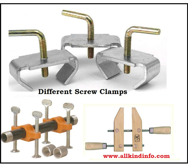
screw clamps for jigs and fixtures

(i) Clamping Screws
Clamping screws are best where small and light work pieces to be clamped.
(ii) Hook Bolts
Hook bolts are also suitable for light purposes and where tip of clamp is inconvenient.
(iii) Bridge Clamp
It is very simple in construction and reliable clamp. The most useful part of this clamp is spring loaded nut..
 (iv) Heel Clamp
Heel clamps consists of three major parts, first plate, second center stud and third the heel.This trap ought to be reinforce at the point where the opening for the stud is removed, by expanding the thickness around the hole.
(v) Latch Clamp
Latch clamp is also known as swing strap clamp is very special type of clamp. This clamp is very useful where work piece is to quickly operate to loading and unloading.Lid or latch can easily swing around the job and easy to clamp.
(vi) C-Clamp
It is most useful item used in the workshops.Locking nut is unscrewed by C-shaped. When the clamp is removed the work piece can free easily. The jaw of the clamps fastened the work piece.
heel,latch and bridge clamps

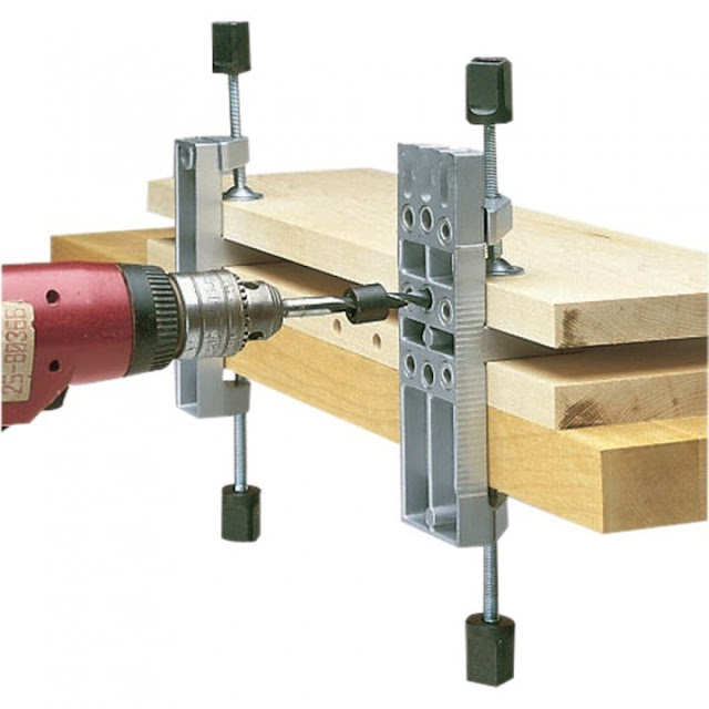
2: Tool Guide or Jig Bushing
Some of the time the firmness of the cutting tool might be in adequate to perform certain machining operations. Then to locate the tool regarding to work piece, use is made of guiding such as jig bushing and templates are used where precision is required.Jig bushed are utilized as a part of penetrating ,boring and drilling,through which the drill passes a bush is used to guide the tool.The diameter of the bush depends on the diameter of the drill.Distinctive sort of bushes are spot welded or screwed with the jig. Headless sort shrubs are press fit into the opening of the work piece. Bushes are general made of a decent grade of  steel to protect solidifying at a reasonably no temperature and to lesson the risk of fire cracking. At some point the bushed for managing devices might be of solid metal. Solidified steel bushes are constantly best to guide drills, reamers and taps etc. There are three types of jig bushes according to american standard.
(i) Press fit wearing bushes
press fit wearing bushes

These bushes are used where accuarcy dos not matter, such as twist drill is used and press fit bushes are guide the tool. These bushes are mounted directly to the jig body.There are two main types of press fit wearing bushes. (a) head less or plain bushes (b) flanged or headed type bushes
(ii) Renewable wearing bushes
renewable wearing bushes

At the point when the guide bushes requires occasional substitution (because of wear of inside diameter of the bush). Its substitution is basically by utilizing a renewable bush. These are of the flanged sorts and sliding fit into the linear bushes, which is installed press fitted into the jig plate. The linear bush gives solidified wear resistance, mating surface to the renewable bush. The renewable bush must be kept prevented from rotating  or lifting with the drill.
(iii)Linear wearing bushes
linear wearing bushes

Linear wearing bushes are also know as master bushes which are mounted or fixed permanently to the jig body.These acts as renewable wearing bushes. These are also with or without head shaped.

MKRdezign

Contact Form

Name

Email *

Message *

Powered by Blogger.
Javascript DisablePlease Enable Javascript To See All Widget